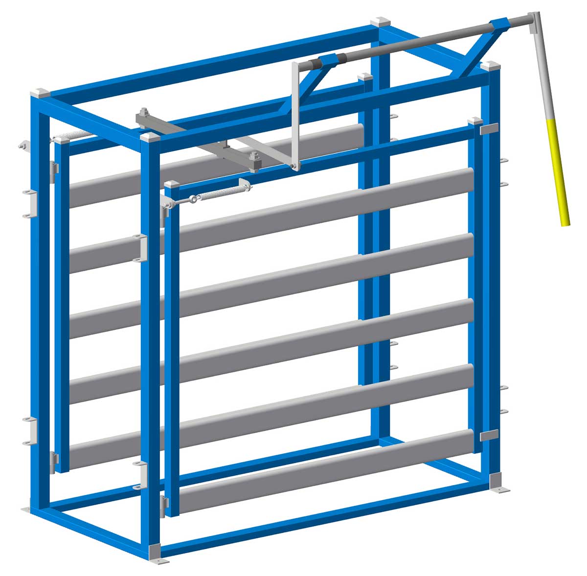
To draft or sort cattle a heavy duty drafting or sorting gate is a necessity. These simple plans will allow you to build your own. The drafting gates can be installed in the race either after or before the crush or squeeze chute.
Free 3 Way Cattle Drafting Gates Plans
| Materials Required | |||
|---|---|---|---|
| Item Number | Material | Length | Quantity |
| 1 | 65x35x2.0 RHS | 2000mm | 2 |
| 2 | 65x35x2.0 RHS | 930mm | 2 |
| 3 | 65x65x2.0 SHS | 2000mm | 4 |
| 4 | 65x65x2.0 SHS | 1870mm | 2 |
| 5 | 65x65x2.0 SHS | 800mm | 2 |
| 6 | 50x50x2.0 SHS | 1600mm | 4 |
| 7 | 115x42 oval cattle rail | 1675mm | 10 |
| 8 | 50x50x2.0 SHS | 1675mm | 2 |
| 9 | 40x8 flat bar | 100mm | 4 |
| 10 | 50x10 flat bar | 150mm | 2 |
| 11 | 50x10 flat bar | 80mm | 2 |
| 12 | 40x8 flat bar | 930mm | 2 |
| 13 | 40x8 flat bar | 28mm | 2 |
| 14 | 40x8 flat bar | 50mm | 2 |
| 15 | 50x8 flat bar | 100mm | 1 |
| 16 | 50x8 flat bar | 520mm | 1 |
| 17 | 40x8 flat bar | 610mm | 1 |
| 18 | 50x50x2.5 SHS | 450mm | 2 |
| 19 | 50x50x2.5 SHS | 90mm | 2 |
| 20 | 50x8 flat bar | 100mm | 1 |
| 21 | 32nb med wall pipe | 1335mm | 1 |
| 22 | 40nb xl wall pipe | 50mm | 2 |
| 23 | 32nb med wall pipe | 1000mm | 1 |
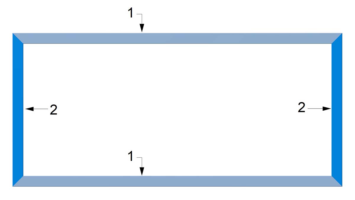
Diagram 1
1. Begin by cutting all of the steel as indicated in the cutting list. Label each with the item number on it using a marking pen and set aside. Take note of the mitre cuts for the RHS to ensure that they are cut the correct way..
2. Tack weld the main floor frame together as shown in diagram 1. Check that the frame is square and fully weld.
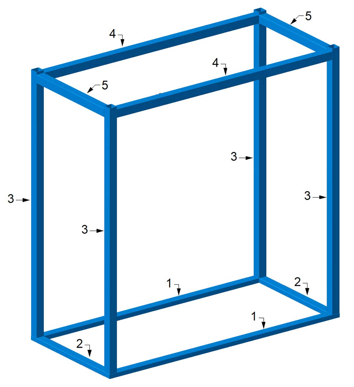
Diagram 2
3. Tack weld items 3, 4, and 5 in position as shown in diagram 2. The top of items 4 are located 30mm down from the tops of items 3. Check that the frame is square and fully weld.

Diagram 3
4. Tack weld items 6, 7 and 8 as shown in diagram 3. Recheck that the gate is square and fully weld.

Diagram 4
5. Weld the hinges in place. Locate the top hinge approximately 100mm down from the top of the gate. Refer to diagram 4.
6. Install the top and lower gate stops as shown in diagram 4.
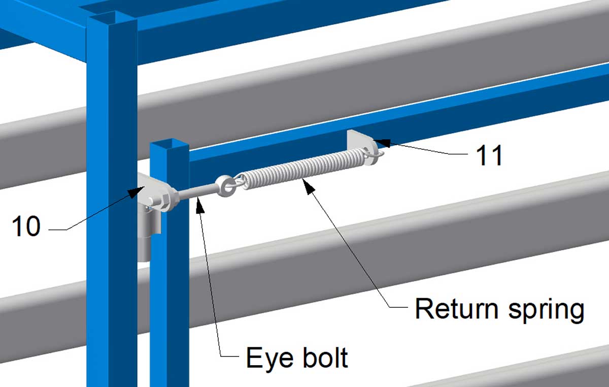
Diagram 5
7. Two heavy duty springs are required to return the gates to the closed position. The springs used will depend on what you can find in your local store, online or already have available which is why we have not specified exact locations of items 10 and 11. The eye bolts and nuts are so that it will make installation of the spring easier and for tension adjustment. Refer to diagram 5.
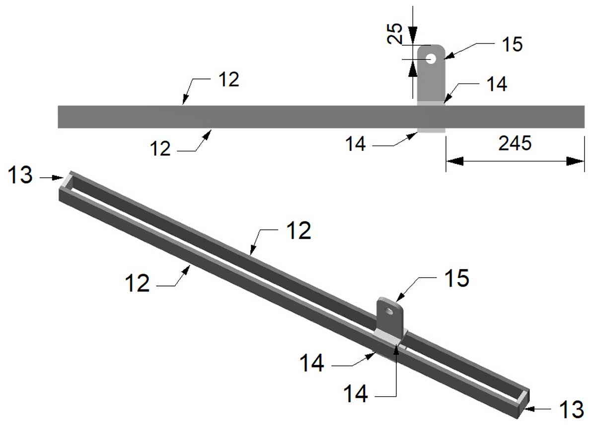
Diagram 6
8. Drill a 18mm hole in item 15 as shown in diagram 6. Assemble items 12, 13, 14 and 15 and weld as shown in diagram 6.
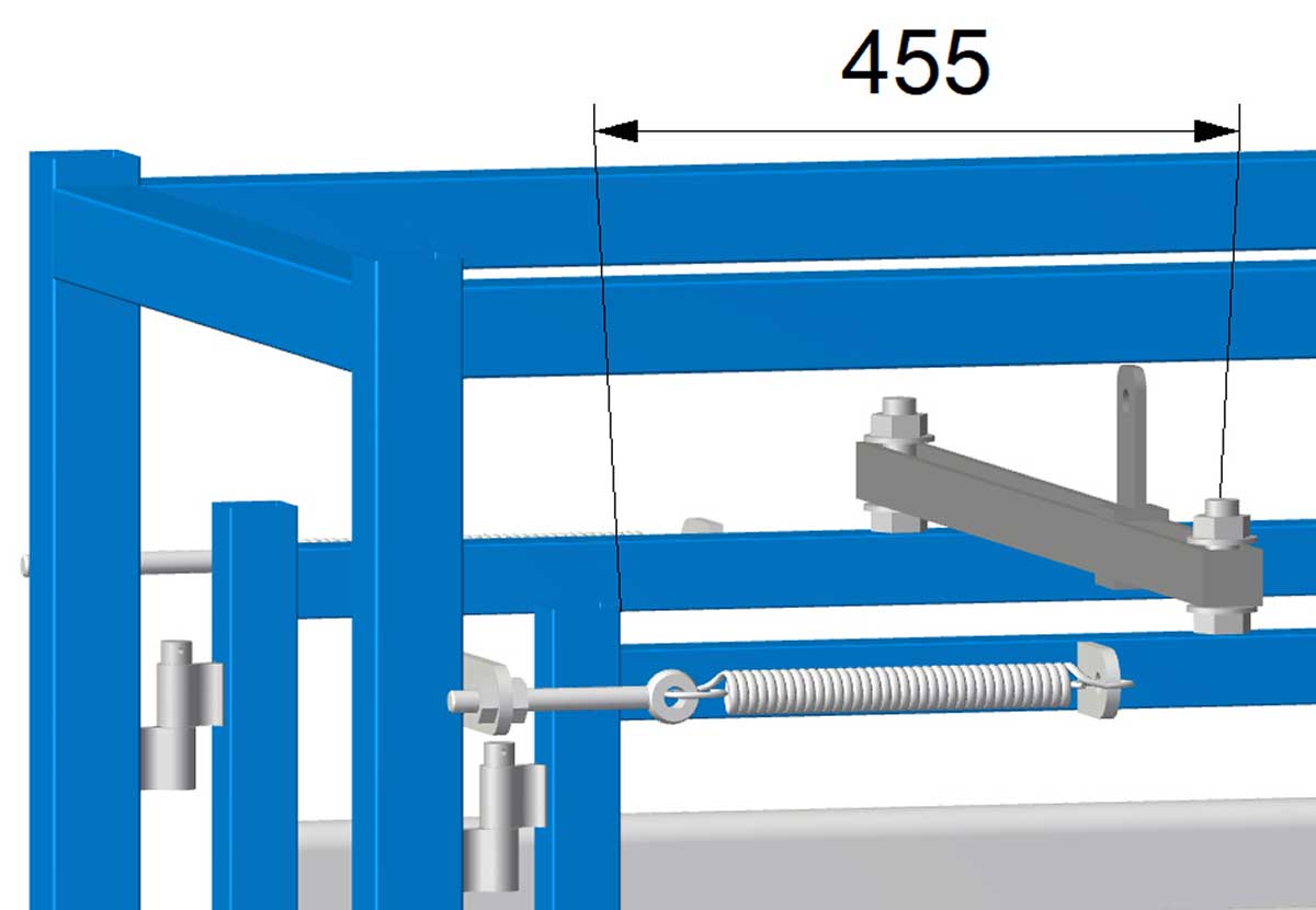
Diagram 7
9. Weld an M24 x 80mm bolt to the top rail of the gates. The centre of the bolt should be 455mm from the inside edge of the gate upright. Ensure that gate linkage assembled in the previous step is able to be install onto the bolts as shown in diagram 7. An M24 flat washer is installed onto the bolts, followed by the gate linkage, followed by another flat washer and then secured with an M24 nyloc nut.
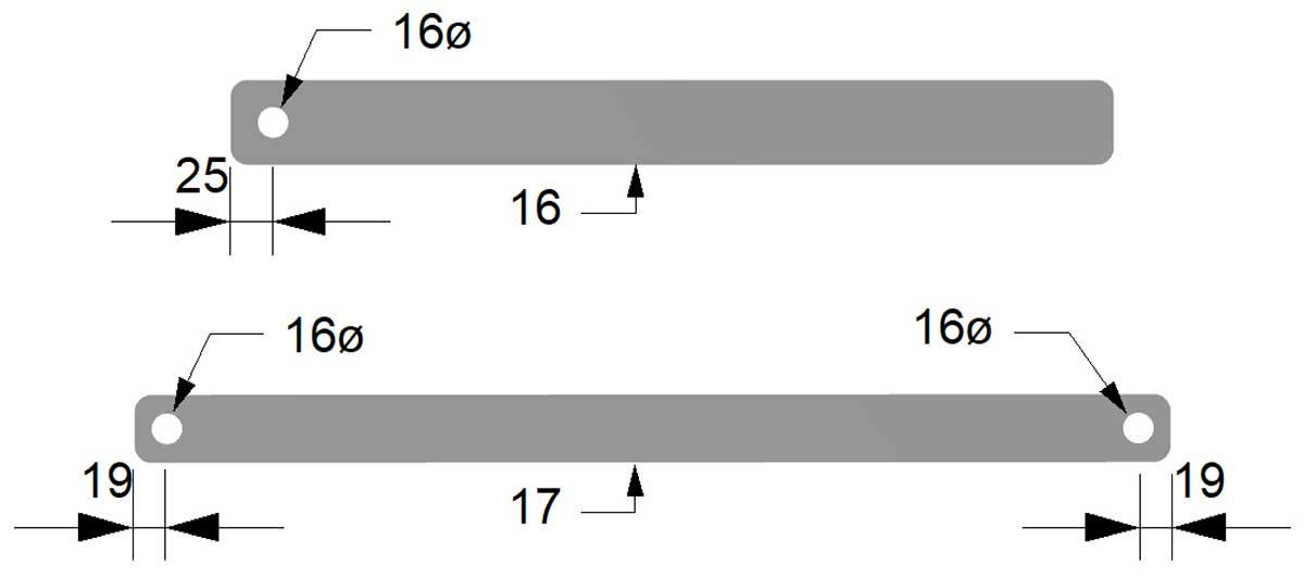
Diagram 8
10. Drill 18mm holes in items 16 and 17 as shown in diagram 8.
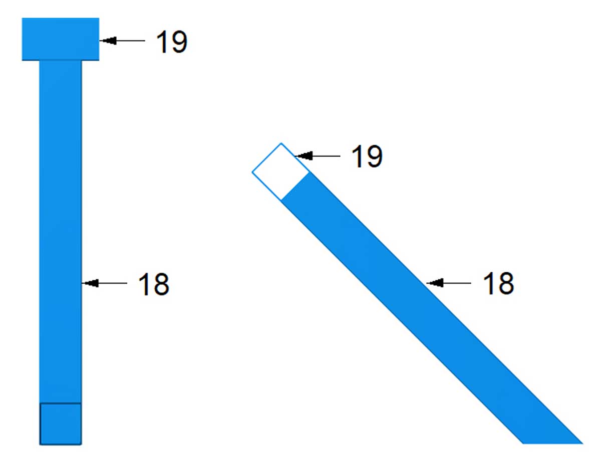
Diagram 9
11. Weld items 18 and 19 as shown in diagram 9.

Diagram 10
12. Weld items 18 and 19 in place. Refer to diagrams 10 and 11.
13. Insert item 21 into the right hand item 19 and slide one of item 22 over item 21. Continue inserting item 21 into the left hand item 19 and slide the remaining item 22 over item 21.

Diagram 11
14. Weld items 22 onto item 21 as shown in diagram 10 and 11.
15. Secure item 17 to the gate link assembly using an M16x40mm bolt and nyloc nut. Secure item 16 to item 17 using an M16x40mm bolt and nyloc nut. Weld the top of item 16 to the end of item 21. Ensure that the two bolts are not overtightened as the linkages need to be able to pivot up and down as well as sideways when the gates are opened and closed.
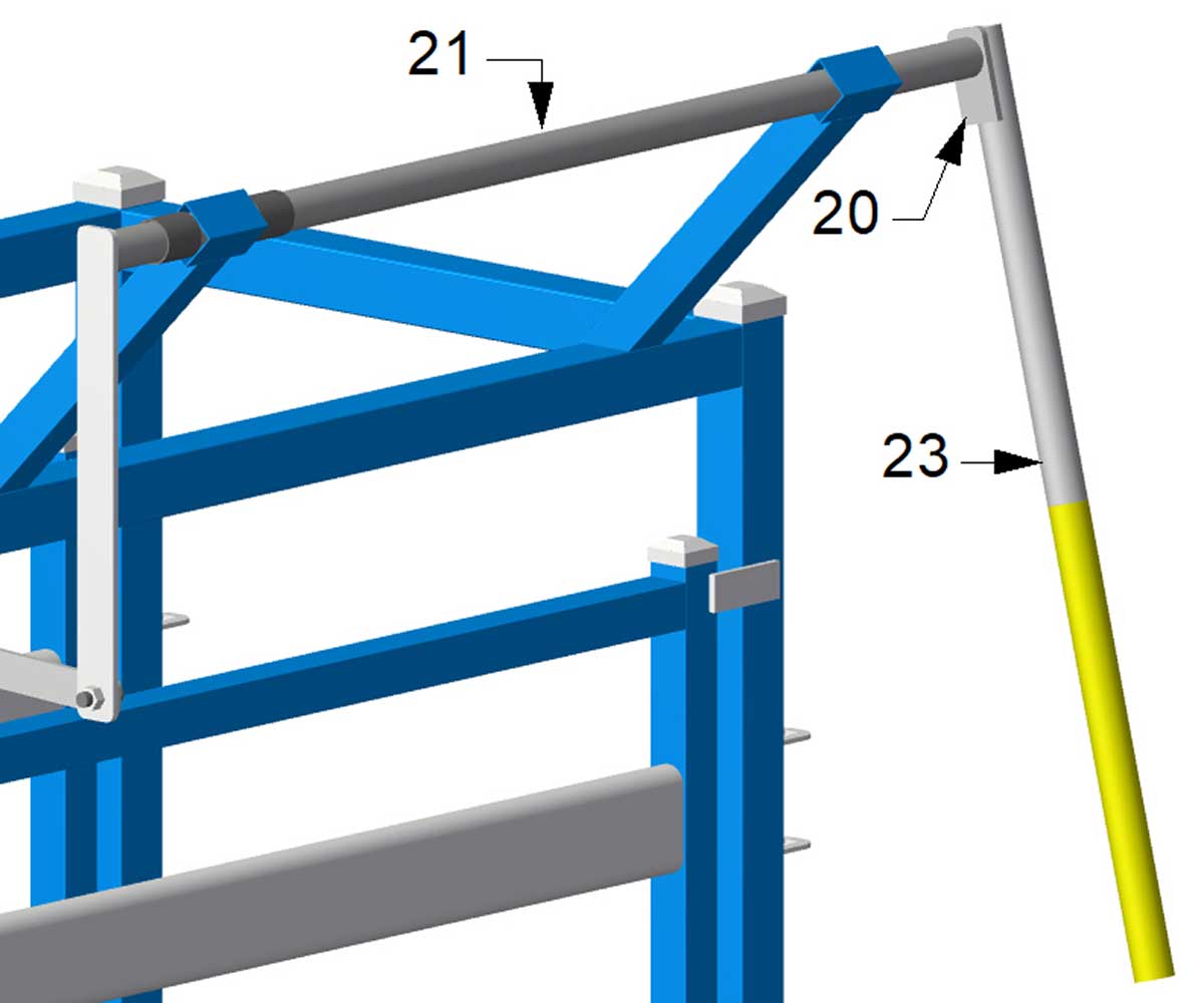
Diagram 12
16. Weld item 20 onto one end of item 23 so that the ends are flush. This assembly is for the handle.
17. Tack weld the flat bar of the handle to the end of item 21. The bottom of the handle should be installed approximately 15 degrees from vertical. Before full welding, ensure that the gates can be operated without the bottom of the handle making contact with the frame. Refer to diagram 12.
18. Install square caps to SHS as required.
19. Clean any welds using a grinding disc or flap disc and paint as required.